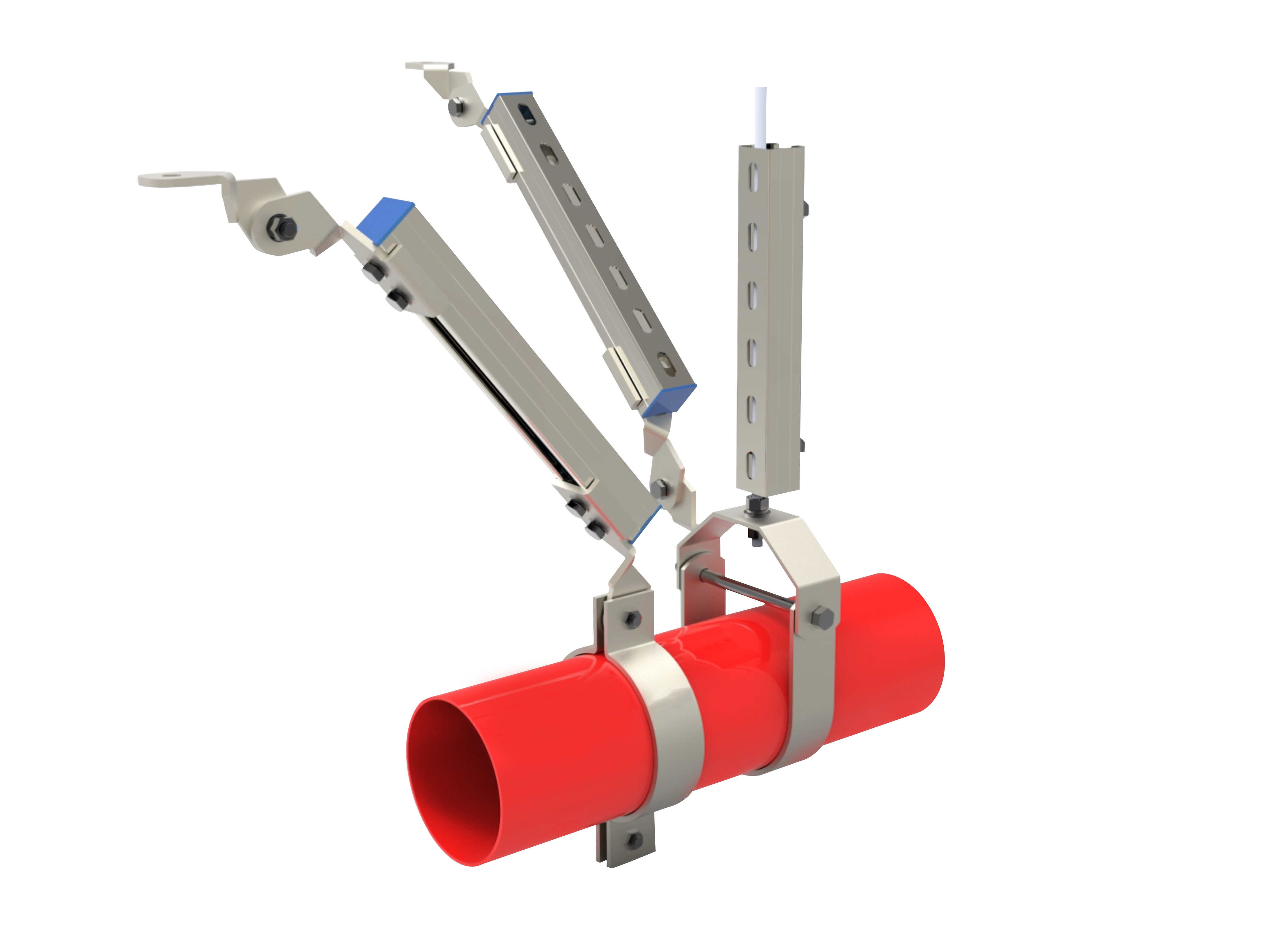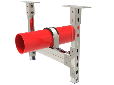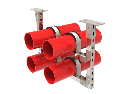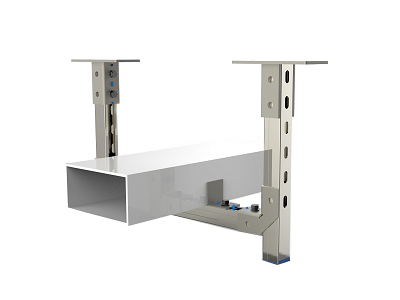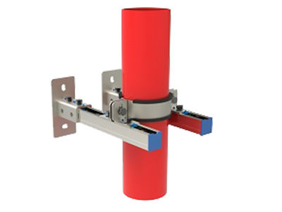

Seismic anchors are post-installed anchoring connectors between M&E seismic bracings and concrete slabs/beams. During earthquakes, they withstand vertical and horizontal bidirectional seismic loads imposed on supports, transfer seismic forces generated by pipelines, cable trays and air ducts to the main building structure, and prevent supports from falling off and pipelines from collapsing to cause personal injuries.
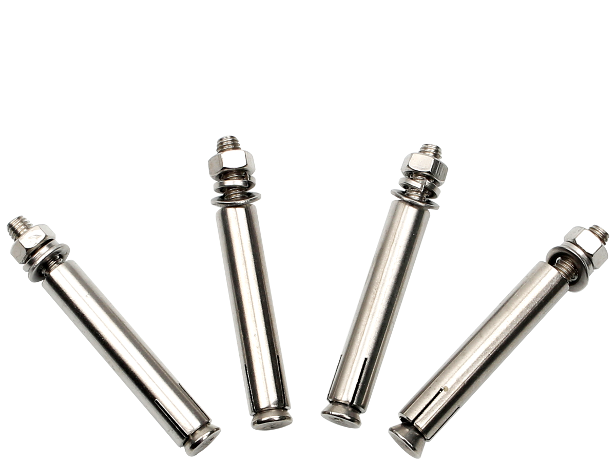
A special drill bit cuts a conical locking recess at the hole bottom. Expansion sleeves spread and embed into concrete to form rigid mechanical interlocks. Reliance on friction is eliminated with no sustained expansion stress. The anchors maintain stable load capacity even in cracked concrete (crack width ≤0.3mm), featuring excellent vibration resistance and anti-fatigue performance without loosening.
Screw Strength: High-strength carbon steel of Class ≥8.8
Anti-corrosion Treatment: Hot-dip galvanizing (Salt Spray Test ≥500h); 304 stainless steel available for humid basements
Mandatory Supporting Documents: Cracked concrete load capacity report, million-cycle fatigue test report, fire resistance test report, seismic certification
Common Sizes: M10, M12, M16 (M12 is the mainstream specification for seismic bracings)
Immediate load bearing right after drilling, no curing waiting time; fast construction, stable load capacity, convenient maintenance and disassembly.
Composed of undercut threaded studs and Grade A injection epoxy adhesive, they bear loads via dual mechanisms: chemical bonding and mechanical undercut interlocking. They produce nearly zero expansion stress, suitable for beam sides, thin slabs and positions with insufficient edge distances.
Heavy-duty seismic bracings for large-diameter fire-fighting pipes, heavy air ducts and dense cable trays; seismic retrofitting of old buildings.
Adhesive requires curing (30–60 minutes at ambient temperature), resulting in low construction efficiency under low-temperature conditions.
❌ Prohibited Products: Standard Expansion Bolts & Ordinary Sleeve Adhesive Anchors
Standard expansion bolts: Loaded merely by friction; prone to sliding and loosening under vibration, highly likely to fail during earthquakes. Explicitly forbidden for seismic load-bearing joints by codes.
Ordinary adhesive anchors: Without undercut interlocks, their load capacity drops sharply in cracked concrete and fails to meet seismic calculation requirements.
Base concrete strength ≥C30; anchoring is not allowed on porous, sanding or honeycombed slabs.
Anchorage calculation shall adopt load values under cracked concrete conditions; load capacity values for intact concrete are not permitted.
Reinforcement scanning shall be performed before drilling to avoid main rebars; drilling holes must be thoroughly cleaned with brushes and high-pressure air blowers, otherwise load capacity will decrease by over 50%.
Edge distance, spacing and effective embedment depth shall strictly comply with the anchor manufacturer’s specification; random reduction is forbidden to prevent concrete splitting.
On-site sampling pull-out test with a sampling ratio of 3%; qualified anchors shall achieve a bearing capacity above 1.2 times the design value.
Complete supporting test reports from the same manufacturer shall be provided for the full seismic system (channel steel, connecting fittings and anchors), which will be key inspection items for supervisors.
Layout positioning and reinforcement detection via rebar scanner
Drill holes to the standard embedment depth with special drill bits
Repeated hole cleaning with brushes and high-pressure air blowers (minimum 3 cycles)
Insert the anchor body and hammer it fully into place until expansion sleeves completely expand and lock into the undercut recess
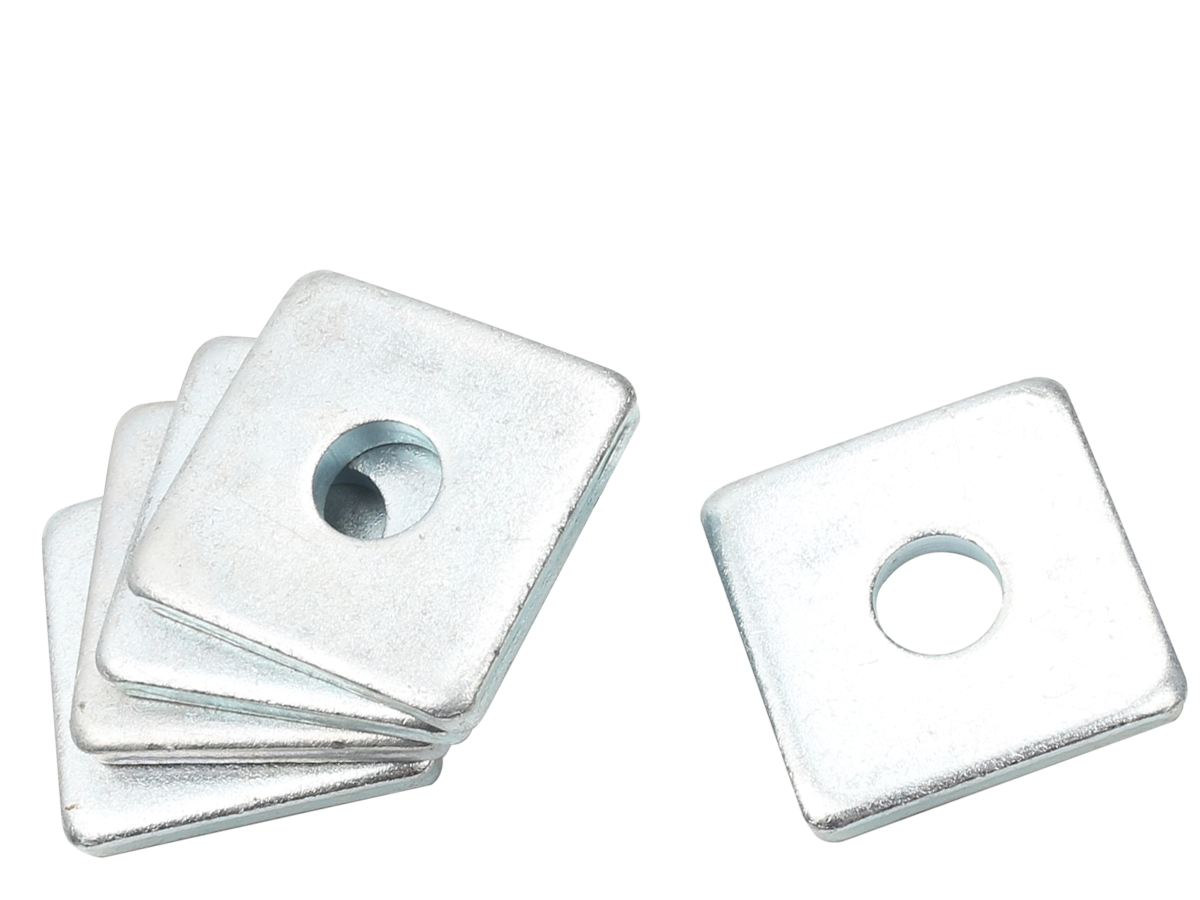
Install seismic base plate, flat washers and spring washers, then tighten nuts to standard torque with a torque wrench
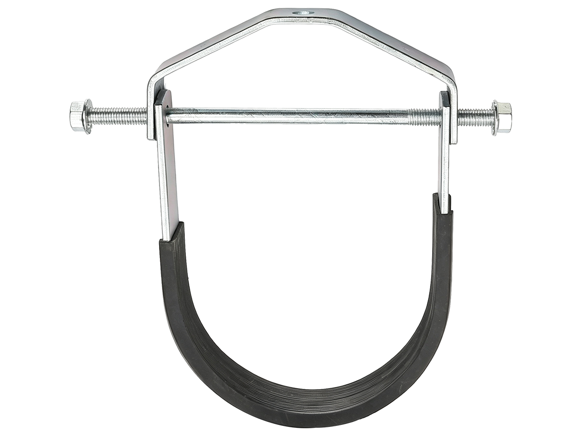
Mount seismic channel steel, diagonal braces and pipe clamps after passing sampling pull-out tests

Hi! Welcome back.
How are you doing?